
Power Supply Check
Check that the unit receives power: verify the main breaker, ensure the correct voltage, and inspect all fuses․ If the fan spins but the heater stays off, the thermostat or relay may be defective․ Swap with known good parts to isolate the fault․ Also, check the main switch and breaker status and no tripping!
Verify Electrical Connections and Fuses
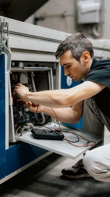
Start by turning off the main breaker․ Remove the panel and locate the main power feed․ Using a calibrated multimeter set to AC voltage, verify carefully the heater receives carefully 120 V residential or 240 V larger systems at inlet terminals․ Inspect each wire for insulation damage, corrosion, or fraying; replace any compromised conductors immediately․ Check the polarity of the connections against the wiring diagram; reverse polarity can cause immediate failure․ Tighten all terminal screws to the manufacturer’s specified torque, ensuring a solid mechanical bond․ Examine the fuse block for any blown fuses; replace them with the exact amperage rating specified in the service manual․ If the heater includes a separate high‑voltage ignition coil, test the coil’s resistance with a multimeter and confirm it falls within the manufacturer’s tolerance range․ Verify that the thermostat wiring is intact and that the relay contacts are free of oxidation․ Document each inspection step, noting any anomalies, and only restore power once all connections are secure and fuses are intact․ This systematic verification eliminates electrical causes before proceeding to mechanical or combustion troubleshooting․ Finally, review the heater’s service history for any prior electrical repairs that might indicate recurring issues․ By methodically verifying every electrical connection and fuse, you can isolate and resolve power supply problems efficiently!!
Thermostat and Control Unit
Check the thermostat’s signal to the fan motor; a bad thermostat or relay often stops the heater․ Swap with a known good unit or use a multimeter to test continuity․ Keep spare fuses, relays, and a replacement thermostat on hand for quick fixes․ and check continuity quickly․
Test Thermostat Functionality and Relay Status
Begin by confirming the thermostat’s power supply: open the thermostat housing, locate the power wires, and use a multimeter set to AC voltage to verify the correct voltage (typically 120 V)․ If voltage is present, move to continuity testing․ Disconnect the thermostat from the control board, then place the multimeter probes on the thermostat terminals․ A functioning thermostat should show continuity when the set temperature is above the ambient temperature and break when below․ If continuity is absent or inconsistent, replace the thermostat․
Next, examine the relay that controls the fan motor․ The relay is usually a small, rectangular component with four or five pins․ Test the coil by applying the supply voltage: a working coil should spark or click, and the relay contacts should close․ If the coil does not energize, replace it․ After confirming the coil, test the contacts by measuring resistance between the normally open (NO) and common (COM) pins while the relay is energized․ A low resistance indicates closed contacts; a high resistance indicates open contacts․ If the contacts fail to close, the relay is faulty and should be swapped with a known good unit․
When swapping components, always use parts that match the manufacturer’s specifications for voltage, current rating, and pin configuration․ Keep a spare set of fuses, relays, and a replacement thermostat on hand, as these are common failure points in gas heaters․ If the heater resumes operation after replacing the thermostat or relay, the issue is isolated․ If the problem persists, the control board or wiring harness may be at fault, requiring further diagnostics or professional service․

Fan and Blower Inspection
Inspect the fan motor for free rotation, listen for roughness indicating bearing wear, clean blades, verify power supply, test relay continuity, and replace any faulty components․ Ensure the blower housing is clear of obstructions and that airflow is unobstructed․ Check fan belt and motor brushes for wear now
Confirm Fan Motor Operation and Bearing Condition
When inspecting the fan motor, check for arcing, which may indicate overheating․ Measure the motor’s drop under load; a drop suggests component․ Inspect the fan’s brackets or loosening, as misalignment can cause․ If bearings are worn, replace them with parts to restore rotation․ After repairs, run a test cycle to confirm the airflow and that the heater’s safety interlocks correctly․ Document measurements and parts replaced forfuture!!!
Verify the fan’s airflow meets the minimum rating for safe operation․ Verify airflow meets the minimum!!!
Begin by inspecting the fan housing for corrosion or mechanical damage․ Remove the cover and check the motor shaft for smooth rotation; any wobble indicates bearing wear․ Use a dial indicator to measure shaft runout; acceptable runout is less than 0․05 mm․ Inspect fan blades for dents or cracks; clean them with a soft brush and ensure proper balance․ Check the bearing assembly for oil leakage; if dry, apply a few drops of high‑temperature grease․ Verify all electrical connections: tighten terminal screws, inspect frayed wires, and confirm voltage matches the motor’s rating․ Use a multimeter to test motor windings for continuity; an open circuit indicates a burned coil․ If the motor runs but is noisy, replace bearings or consider a motor replacement if extensive․ After fixes, re‑assemble the fan, restore power, and run a short test cycle to observe fan speed․ Measure airflow with an anemometer; it should be within 10% of spec․ If airflow is low, inspect ductwork for blockages, leaks, or improper bends that reduce draft․ Finally, document all findings, including bearing condition, shaft runout, blade condition, electrical test results, and airflow measurements․ Record any parts replaced and the date of the inspection․!!!!!

Ignition and Spark System
Check the igniter for arcing, test spark plug voltage, and inspect the high‑voltage coil․ Swap a known good coil if the spark is weak․ Verify the control board’s relay status; a faulty board can prevent ignition․ Use a multimeter to confirm voltage at the spark plug․ If the spark fails, replace the igniter coil․
Inspect Igniter, Spark Plug, and High‑Voltage Coil
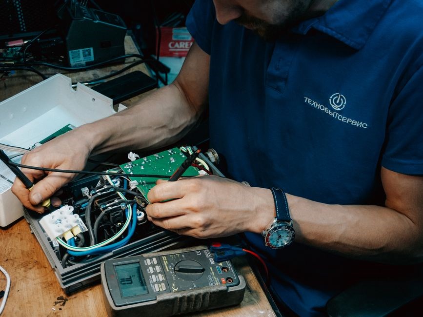
Begin by turning off the gas supply and disconnecting the power to the heater․ Remove the access panel and locate the igniter assembly․ Inspect the igniter for visible cracks, burn marks, or a dull surface; a damaged igniter will fail to generate the necessary spark․ Use a multimeter set to the high‑voltage range to test the igniter’s continuity; a reading of infinite resistance indicates a fault․ Next, examine the spark plug․ Remove it carefully, clean any soot or deposits, and check the electrode gap․ The gap should match the manufacturer’s specification; a gap that is too wide or too narrow will prevent proper ignition․ Test the spark plug voltage by reconnecting it to the high‑voltage coil and observing the spark with a spark tester or by listening for a clear, bright spark․ If the spark is weak or absent, replace the plug․ Finally, inspect the high‑voltage coil․ Look for any signs of insulation breakdown, such as cracks or discoloration․ Measure the coil’s resistance with a multimeter; a reading outside the specified range (typically 200–300 Ω for most units) indicates a defective coil․ If the coil fails the test, replace it․ After replacing any faulty component, reassemble the panel, restore power, and re‑engage the gas valve․ Perform a test burn to confirm that the igniter, spark plug, and coil are functioning correctly and that the heater ignites reliably․ If the heater still fails to ignite, further diagnostics on the control board or relay may be required․
Ensure all wiring connections are tight and free of corrosion․ Inspect the wiring harness for frayed insulation or broken conductors that could interrupt the spark signal․ Verify that the grounding strap is securely attached to the metal chassis; a poor ground can cause intermittent ignition failures․ If the heater has a built‑in diagnostic mode, enter it to read any stored fault codes related to the ignition system․ These codes can pinpoint whether the issue lies with the igniter, spark plug, coil, or control board․ Finally, after confirming all components are in good condition, reset the system by cycling the power and gas valve to clear any transient faults․ A successful test burn should produce a steady flame and no error codes․ If problems persist, consult the manufacturer’s service manual for advanced troubleshooting or consider professional service․ Remember to wear insulated gloves and safety glasses during inspection․ Keep the work area dry to prevent accidental short circuits․ Keep a record of any changes made for future reference․ If the heater still does not ignite after these steps, the issue may be with the control board’s ignition timing or a defective relay, which would require specialized diagnostic tools or replacement․ Additionally, verify that the heater’s internal temperature sensor is functioning, as a faulty sensor can falsely indicate a high temperature and shut down the ignition cycle․
Gas Supply and Pressure
Verify the main gas valve is fully open and inspect supply lines for leaks, kinks, or corrosion․ Use a manometer to confirm regulator output (5–15 psi)․ If pressure is low, adjust or replace the regulator; if high, trim or replace it․ Tighten all fittings․ Check for proper venting and ensure no blockages․

Check Gas Valve, Supply Lines, and Pressure Regulator
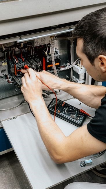
When the heater fails to ignite or shuts down abruptly, the first suspect is often the gas supply․ Inspect the main gas valve for proper operation: it should open fully and remain steady under pressure․ A partially closed valve can cause insufficient fuel flow, leading to flame failure or low heat output․ Examine the supply lines for visible damage—cracks, pinched sections, or corrosion can restrict flow and create dangerous pressure drops․ Verify the regulator delivers the manufacturer‑specified pressure (typically 5–15 psi)․ A regulator set too low will starve the burner, while one set too high can overload the system and trigger safety interlocks․ If the regulator appears faulty, replace it with a unit that matches the heater’s rating․ Finally, check the regulator’s mounting and connections for leaks by applying a soapy water solution; bubbles indicate a compromised seal that can lead to gas loss or pressure instability․
When the heater fails to ignite or shuts down abruptly, the first suspect is often the gas supply․ Inspect the main gas valve for proper operation: it should open fully and remain steady under pressure․ A partially closed valve can cause insufficient fuel flow, leading to flame failure or low heat output․ Examine the supply lines for visible damage—cracks, pinched sections, or corrosion can restrict flow and create dangerous pressure drops․ Verify the regulator delivers the manufacturer‑specified pressure (typically 5–15 psi)․ A regulator set too low will starve the burner, while one set too high can overload the system and trigger safety interlocks․ If the regulator appears faulty, replace it with a unit that matches the heater’s rating․ Finally, check the regulator’s mounting and connections for leaks by applying a soapy water solution; bubbles indicate a compromised seal that can lead to gas loss or pressure instability․
Ventilation and Flue Path
Inspect the flue for blockages, ensuring clear airflow․ Check for cracks or corrosion that could leak gases․ Verify proper draft by observing flame color; a blue flame indicates good draft, while a yellow tip suggests insufficient airflow․ Seal any leaks to maintain safety․ Check for soot buildup that can restrict airflow fast․
Examine Flue for Blockage, Leaks, and Proper Draft
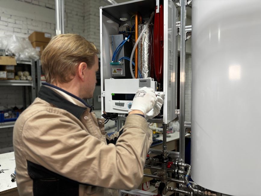
Begin by visually inspecting the entire flue path from the combustion chamber to the exterior vent․ Look for obstructions such as bird nests, debris, or accumulated soot that can impede airflow․ Use a long, flexible inspection camera or a flashlight with a long handle to peer into concealed sections․ If you spot any blockage, carefully remove it with a brush or a vacuum designed for flue cleaning, ensuring the vent remains clear for safe operation․
Next, assess the integrity of the flue lining․ Inspect for cracks, corrosion, or gaps that could allow gas leaks or reduce draft efficiency․ A small crack may be identified by a faint discoloration or a subtle change in the flue’s surface texture․ If you detect any damage, replace the affected section or apply a high‑temperature sealant approved for gas appliances․ Check for rust on metal liners; extensive rust warrants a liner replacement to maintain structural integrity․
To verify proper draft, observe the flame when the heater is operating․ A steady, blue flame indicates adequate draft, while a yellow or flickering flame suggests insufficient airflow․ Measure the draft pressure using a manometer; a typical residential gas heater requires a draft of 0․1 to 0․3 inches of water column․ If the draft is below spec, check for vent obstruction or a mis‑aligned vent pipe, and adjust accordingly to restore optimal airflow․
Perform a smoke test to detect leaks: introduce a small amount of smoke into the flue and observe if it escapes at any point․ If smoke appears outside the vent, seal the leak with a high‑temperature silicone sealant․ Additionally, check for condensation inside the flue; excessive moisture can corrode the lining․ Use a moisture meter to gauge internal humidity and consider installing a flue dampening system if moisture is persistent․
Finally, ensure the vent termination is correctly positioned․ The vent should exit at least 3 feet above roof level and be angled upward to promote natural draft․ Verify that the termination does not face into a windward direction that could cause backdrafting․ Document all findings in a maintenance log, and if any condition is not met, adjust the vent or consult a licensed technician for a comprehensive evaluation; Routine annual cleaning and inspection are essential for safe, efficient operation․

Safety Sensors and Diagnostics
Check the flame sensor for soot buildup, ensure the pressure switch trips correctly, and read diagnostic codes via the control panel․ Reset codes after clearing faults, then retest to confirm safe operation․ Replace faulty parts; verify continuity with a multimeter․ and test OK
Verify Flame Sensor, Pressure Switch, and Use Diagnostic Codes
Begin by inspecting the flame sensor for soot or corrosion; a dirty sensor can prevent ignition․ Clean with a fine abrasive pad or replace if damaged․ Next, test the pressure switch by disconnecting the gas line and observing the switch’s indicator light or using a multimeter to confirm continuity at the correct pressure range․ A faulty pressure switch will trip the system and trigger error codes․ After confirming hardware integrity, access the heater’s diagnostic interface—usually a small LCD or a series of LEDs on the control panel․ Enter the diagnostic mode (consult the unit’s manual for the specific key sequence) and read any stored error codes․ Common codes related to flame detection (e․g․, 0x12, 0x23) or pressure (e․g․, 0x34) indicate the component needing replacement․ Clear the codes, reset the unit, and run a full test cycle to ensure the heater operates safely and the error lights remain off․ If errors persist, re‑inspect the wiring harness for loose connections or corrosion, and verify that the control board’s firmware is up to date․ Proper sensor and pressure switch function, diagnostic feedback operation․!!!! If the flame flickers or extinguishes, check for gas pressure issues, ensure the pilot assembly is clean, and verify that the control board’s electronic timing is correct․ After confirming all parts, reset the unit run a full cycle!!!